Clean Agent Testing Door Fan ensures passage of discharge tests
Prior to 1989 several progressive installers found a unique way to ensure that they would always pass the discharge test. They used a fan mounted in a doorway to create a pressure which allowed them to locate hidden leaks using chemical smoke. When the leaks were sealed, the room would always pass the discharge test. It worked so well that the discharge test has now been replaced by the door fan test.
Door Fan replaces the discharge test
Now, both NFPA 2001 and 12A req- uire an enclosure integrity test (sec- tion 4-7.2.3) as part of the acceptance procedure for all clean agent sys-
tems. This includes halocarbon and inert agents. The comprehensive test and calculation procedure predicts how long the agent would stay in the room if it were ever discharged.
In the past, enclosures were often designed merely to pass the discharge test. This often left rooms with fire barriers on only 5 sides with the top completely open - often only ceiling tiles stood between the protected enclosure and an adjacent unprotected area.
Smoke or fire could readily enter from above. The discharge test only verified agent distribution in one location, usually the most favorable. This may have led to assuming that other approval steps could be overlooked. To make matters worse, the discharge test was never repeated. The room leakage would increase steadily, compromising the system from day one.
Now, the EPA, IRI, FM, other insurers, Fire suppression equipment manufacturers, and the FSSA all encourage door fan tests on every installation. Door Fan tests should be repeated annually or whenever extra holes are made in the enclosure.
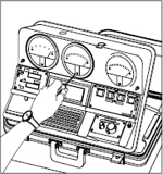
What is a door fan test?
The door fan itself merely measures the size of holes in the enclosure and the pressures that may exist across them. The computer on board does the rest of the simulation and comes up with the prediction. The software walks the user through all the steps in a controlled way to ensure each step is done in accordance with NFPA.
Measuring static pressures
In some cases damper or duct leakage cause a static pressure in the room. This static pressure pushes the agent out faster and is taken into account in the calculations.
Measuring total room leakage
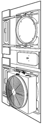
The door fan is temporarily installed in a doorway leading from the protected space (or test room) to a large open area or outdoors.
The fan speed is adjusted to obtain a pressure between the test room and the volume surrounding the test room.
This pressure (usually 10 to 15 Pa or 0.04" to 0.06" w.c.) is similar to the steady state pressure (column pressure) exerted by the agent at floor level at the start of the retention period.
The computer converts flow and pressure readings into an Equivalent Leakage Area (ELA), or the total area of all the cracks, gaps, and holes in the test room.
The measurement is done by first blowing air out of the room (depressurization) and then into the room (pressurization). The two readings are averaged to reduce errors due to HVAC operation, wind and faulty gauge zeroing.
One-way leaks are almost never a factor.
Measuring lower leaks
Below ceiling leaks can be measured separately using a flex duct or plastic on the ceiling to neutralize ceiling leaks. These techniques eliminate the upper leaks for the purpose of measuring the more important lower leak. Both leaks are then used to make a more accurate prediction.
All other variables such as room volume and height must be re-measured on site.
Predicting the retention time.
Upon discharge, the agent mixes violently resulting in a homogeneous mixture. Pressures created in the first few seconds of discharge (referred to as dynamic discharge pressure) are ignored in the retention time prediction model because they are so short and because large factors for loss are already allowed for in the concentration formula.
After discharge, the heavier-than-air agent pressing down upon the floor creates a small positive pressure. Flow develops whenever holes have pressure across them. The greater the pressure and the larger the hole, the greater the agent lost. As the agent runs out the bottom, a small negative pressure develops at the top. This pulls air in through the higher level leaks. Each agent creates a slightly different pressure as indicated by the densities as shown in NFPA 2001.
If the room’s air-moving equipment is off during the retention period, the agent will drain out-much like water out of a hole in a bucket. Air will then flow in through the upper leaks.
The intersection between the pool of agent below and clean air above is referred to as the agent/air interface. This is called the descending interface case. This interface drops, as agent is lost from the room through leaks in the floor and lower wall area. Air from outside the room replaces the lost agent by infiltrating through leaks in the upper half of the room.
If air-moving equipment is left on during the retention period, the infiltrating air will continually mix in with the agent. This is called the continual mixing case. The concentration at the floor will decay at the same rate as the concentra
Door Fan compared to discharge test results
Differences between this prediction and actual retention times are mostly due to leak location. If say 200 sq. in. of holes are distributed 50/50 ( 100 in the ceiling and 100 in the floor), the prediction will be very close to an actual discharge test. Let’s say the result is 10 minutes. But, if they’re actually distributed 75/25, then the discharge test result would be 20 minutes but the prediction would still be 10 minutes because the first prediction always uses the worst case 50/50 distribution.
A second, more accurate prediction may be done if the below ceiling leaks can be measured or accurately estimated. There are three ways to do this. The distribution can be measured with a special flex duct apparatus or by taping over the ceiling to isolate the below ceiling leaks. It can also be estimated after a detailed inspection. The result is a longer retention time than the 50/50 assumption, although, typically the door fan test is much more conservative than an actual discharge.
This conservatism is an advantage because new clean agents have less tolerance for leakage than did the old Halon systems. Halon protected rooms could lose over 50% of agent concentration before the fire could re-ignite. The new agents are more critical and can normally only lose about 20% before re-ignition.
Optimize room design
…for sufficient retention time.
The computer predicts a time for the descending interface to reach the minimum protected height. Or, if there were continual mixing during the retention period, for the concentration to fall to the minimum that would prevent re-ignition after the hold time.
It is up to the specifying engineer to come up with a retention time that is both adequate and an enclosure design that can reasonably be built tight enough. Often the general contractor finds himself rebuilding a room that was not designed to be tight enough to hold agent.
In general there are 5 guidelines to follow that will ensure a properly compartmentalized hazard. These techniques can also be looked on as part of the passive fire protection designed into the enclosure.
First, run walls slab to slab. Include construction details that would allow for sealing of the wall to the upper slab.
Second, in enclosures where the walls do not go slab to slab, consider eliminating the use of T-bar suspended ceilings. Use a solid Sheetrock ceiling with access hatches and facility to walk above it.
Third, maximize the room height and volume. Place the ceiling as high as possible. The greater volume of clean agent in the enclosure, the more reserve and the greater the protection.
Fourth, select an appropriate retention time for the specific enclosure. NFPA 2001 states “... the design concentration ... shall be maintained for a sufficient period of time to allow effective emergency action by trained personnel”. I suggest the following guidelines as being the minimum leakage that can be obtained in small enclosures. In fact, the room size dictates the maximum retention time that can practically be achieved.
For example: a remote site where re-ignition was possible and where it would take 30 minutes for a responsible party to arrive, should be specified as 30 minutes. On the other hand, a small room with little or no potential for a deep-seated fire and where personnel would respond within 5 minutes would need a retention time of 5 minutes. 2001 does not recommend any specific time and states that the AHJ must ultimately decide what is appropriate.
The minimum leakage areas shown in the second row are more in keeping with how tight rooms can be made as they get smaller. For example each room regardless of size must have a door and door usually leak about 5 to 20
sq.in. depending on how well they are weather-stripped. Reducing the total leakage down to the 7
sq.in. that would be required to achieve a 10 minute hold time in a 350 cu. ft. room is not really practical.
Fifth, if protection is required at the ceiling or in the upper 80% of the room, continual mixing of the agent during the retention time should be considered. In this case, start with the highest possible concentration and specify the minimum that it can fall to over the retention time. The gap between these two must be at least 20% to allow for leakage.
Immediate free quote
Contact us for an immediate free quote.
Our quality is certified
Gielle makes its products inaccordance with UNI EN ISO 9001, UNI EN ISO 14001,
SA8000:2001 certified quality standards
In accordance with established maritime standards
Gielle’s systems solutions have been tested and approved by marine regulatory agencies throughout the world.
Worldwide installation and service.
No matter where your vessel puts into port. From
New York to Dubai, we perform whatever service is necessary including installation,
retrofit, recharge, maintenance and
emergency repair.
It's our global commitment to keeping your Gielle systems functioning perfectly and in
accordance with applicable Marine fire protection regulations.
The right approvals and certifications.
Gielle Fire Systems' products carry an impressive range of Type
Approvals and Flag Administration Approvals.
System design, installation & service
Gielle can provide the services (design and installation, retrofit, recharge,
an d maintenance) necessary to keep your system functioning
properly and in compliance with all applicable
Marine fire protection regulations.
We provide complete stationary and mobile fire
protection solutions from risk analysis via technical design to
installation.
Gielle is the leading fullservice
provider for fire protection in Europe and one of
the leading companies worldwide.
Marine, naval and offshore fire protection
Products from the Gielle Fire Suppression have been
developed to meet not only the needs of today, but to also
comply with evolving marine requirements, including
environmental issues, local regulations and more. To every
extent possible, we engineer the ability to upgrade our
equipment directly into our product lines. In many cases, this
gives owners the ability to avoid entire system replacements
when conditions change. Each design innovation is supported
by such important services as ongoing safety documentation.
Immediate free quote
Contact us for an immediate free quote.
 Call us +39 0803118998
 E-mail: